Free
Shipping


The Braemar THM 516 is a gas ducted heating unit, and the PCB Circuit Control Board (Modulating Control Board, MCB) with Part Number: 640365 is an essential component that manages the heater's operation. The PCB (Printed Circuit Board) is responsible for controlling the various functions of the heater, such as the ignition process, fan operation, and temperature regulation. The MCB (Modulating Control Board), in particular, helps regulate the modulation of the heater, which adjusts the burner and fan speed to maintain a consistent temperature and enhance energy efficiency.
Function: The MCB controls the entire heating process. It ensures the burner operates at the correct intensity and modulates the fan speed based on the set temperature and demand for heating.
Part Number: 640365: This is the specific part number for the PCB circuit board used in the Braemar THM 516 NG (Natural Gas) ducted heater.
Compatibility: This part is specifically designed for the Braemar THM 516 NG ducted heater. Using the correct PCB is critical to ensure compatibility and proper functionality.
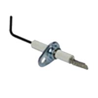
Ignition Control:
The PCB regulates the ignition process, activating the spark igniter and monitoring the flame sensors to ensure safe operation.
Fan Speed Modulation:
The modulating control board adjusts the speed of the fan based on the heating needs. It ensures efficient air distribution and reduces energy consumption by modulating the fan speed as needed.
Temperature Regulation:
The board communicates with the thermostat and adjusts the burner and fan based on the set temperature, helping to maintain a consistent and comfortable room temperature.
Safety Mechanisms:
The PCB monitors various safety sensors (e.g., flame sensors, pressure switches) to prevent hazardous situations, such as unburned gas accumulation or overheating.
Error Codes and Diagnostics:
Many PCBs are equipped with diagnostic features. If the system encounters an issue (e.g., ignition failure, flame detection failure), the board will trigger an error code that can be referenced for troubleshooting.
Screwdrivers (Philips and flathead)
Multimeter (for testing electrical connections)
Replacement PCB (Part Number: 640365)
Turn Off Gas and Power:
Before starting, ensure that both the gas supply and electrical power to the heater are turned off to avoid any risk of electrical shock or gas leakage.
Remove the Heater's Access Panel:
Use a screwdriver to remove the panel that covers the PCB and internal components of the heater.
Locate the Old PCB:
Identify the existing control board (PCB) inside the heater. This will likely be connected to various wiring for the ignition, fan, and temperature sensors.
Disconnect the Wires from the Old PCB:
Take note of how each wire is connected to the old PCB before removing them. It's a good idea to take a photo or label the wires for easy reinstallation.
Carefully disconnect all wiring from the old board.
Remove the Old PCB:
Unscrew or unclip the PCB from its mounting position and carefully remove it.
Install the New PCB (PN: 640365):
Mount the new PCB in place of the old one, ensuring it’s securely fixed.
Reconnect all the wires exactly as they were connected to the old PCB (using the photo or labels you made earlier as a reference).
Check All Connections:
Double-check that all wires are connected correctly and securely, as loose or incorrect connections can prevent the heater from operating properly.
Reassemble the Heater:
Once the PCB is installed and the wiring is connected, replace the access panel and secure it with screws.
Turn On the Power and Gas:
Turn the power and gas supply back on and test the heater.
If the PCB is functioning correctly, the system should start up, and the modulating fan should operate smoothly. Monitor the heater for any error codes or unusual behavior.
Verify Operation:
Ensure that the heater is heating properly and that the fan speed is modulating based on the temperature settings. If the unit is not functioning correctly, check the error codes and refer to the troubleshooting section.
If you experience issues after replacing the PCB, consider the following:
No Ignition or Heater Not Starting:
Check the power supply to the unit (is the power switch on?).
Verify the wiring is connected properly to the PCB.
Test the spark igniter and flame sensors to ensure they are functioning correctly.
Error Codes:
Refer to the heater's user manual for the list of error codes that the system may display. Each error code corresponds to a specific issue, such as flame sensor failure, ignition failure, or fan motor issues.
Fan Not Modulating:
If the fan is running at a constant speed, ensure that the fan motor and fan speed control connections are properly secured on the PCB.
Verify that the temperature sensor is functioning and correctly connected to the control board.
Check for Faulty PCB:
If all wiring and components are correctly installed and the system is still malfunctioning, it’s possible that the new PCB is defective. In that case, you may need to replace it with another unit.
| SKU | 19940 |
| Brand | Braemar |

Add your favourites to cart

Select Afterpay at checkout

Log into or create your Afterpay account, with instant approval decision

Your purchase will be split into 4 payments, payable every 2 weeks
All you need to apply is to have a debit or credit card, to be over 18 years of age, and to be a resident of country offering Afterpay
Late fees and additional eligibility criteria apply. The first payment may be due at the time of purchase
For complete terms visit afterpay.com/terms